Showing posts with label Op-amp Circuit. Show all posts

Simple delay time circuit

Diposkan oleh Electronics Blog | 15:27 | | 0 komentar »

We can use series RC circuit and voltage comparator to generate
a time delay. Two resistors R2 and R3 are used as a voltage divider
which applies about two-thirds of the Vcc voltage to the positive
comparator input The delay time after the Vin change form low to
high will be around one time constant


Time constant = R1C1 = 100K * 10uF = 1 seconds.

The delay time can be adjust by adjusting R1 or change C1


Technorati Tags:

On-Off Control With Hysteresis Circuit

Diposkan oleh Electronics Blog | 15:23 | | 0 komentar »

We can use inverting Schmitt trigger circuit for this application
Inverting Schmitt trigger
the circuit can be view as an inverting –type threshold detector whose
threshold is controlled by the out put since the output has two stable
state, this threshold has two possible values,namly

Vth = R1*Voh/(R1+R2)
Vtl = R1*Vol/(R1+R2)

On-Off Control With Hysteresis Circuit
The hysteresis width is defined as
Hw = Vth – Vtl = R1*( Voh – Vol )/( R1 + R2 )
Behaviour of circuit show in below picture.


Sample waveformsOn-Off Control With Hysteresis Circuit


Technorati Tags:

Simple Large Fan-In AND Gate circuit

Diposkan oleh Electronics Blog | 15:17 | | 0 komentar »

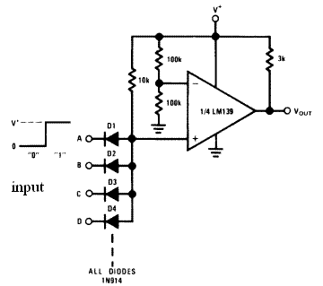
We can make simple Large Fan-In AND Gate circuit by one Voltage Comparators from circuit below

Vout = A and B and C and D and ….

This circuit is application of LM139
LM139
Low Power Low Offset Voltage Quad Comparators
The LM139 series consists of four independent precision
voltage comparators with an offset voltage specification as
low as 2 mV max for all four comparators. These were
designed specifically to operate from a single power supply
over a wide range of voltages.

All pins of any unused comparators should be tied to the
negative supply.

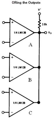
The output of the LM139 series is the uncommitted collector
of a grounded-emitter NPN output transistor. Many collectors
can be tied together to provide an output OR’ing function.

Vo = A or B or C


Technorati Tags:

Constant current source circuit

Diposkan oleh Electronics Blog | 15:11 | | 0 komentar »

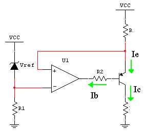
We can use a voltage reference turn into a Constant current source
circuit and use pnp-transistors for current-boosting
Constant current source circuit
By op amp action ,the voltage across R is away Vref , give
Ie = Vref / R

Ie = Ib + Ic = (Ic/B) + Ic

Ic = [B/(B+1)] *Ie

Io = Ic = [B/(B+1)] * Vref / R about Vref / R
VL = Io*RL
Where maximum voltage of Vl(max) <>

We can adjust output current by adjust current setting resistance R


Technorati Tags:

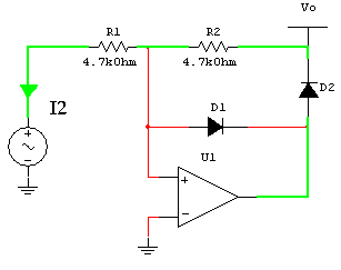
Half wave precision rectifiers circuit

Diposkan oleh Electronics Blog | 15:03 | | 0 komentar »

A half-wave rectifier is a circuit that passes only the positive or only the negative
Portion of a wave ,while blocking out the other portion
Rectifiers are impremented using diodes. The nonzero forward-voltage drop of
A pactical diode may cause intolerable errors in low-level signal

Proceeding of half-wave precision rectifiers circuit we separate are two case
Case 1 Vi > 0 negative input of op amp is higher positive input ,the op amp
Output = 0 ,I1 will flow through R1 and D1 ,hence Vo = 0
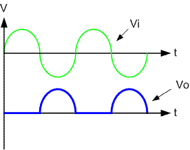
Half wave precision rectifiers circuitCircuit behavior
Vo = 0 for Vi > 0
Vo = -(R2/R1)Vi for Vi <>
Example waveform

Half wave precision rectifiers circuitTechnorati Tags: ,

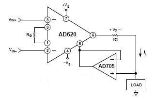
The AD620, along with another op-amp and two resistors, makes a precision current source circuit.
Precision Voltage-to-Current Converter Circuit The op-amp buffers the reference terminal to maintain good CMR. The output voltage, VX, of the AD620 appears across R1, which converts it to a current. This current, less only the input bias current of the op amp, then flows out to the load.
where
Vx = [(Vin+) – (Vin-)] * G
IL = Vx / R1
Circuit operates on 1.8 mA, ±3 V

Gain(G) is resistor-programmed by Rg
Rg = 49.4K ohm / (G-1)
Technorati Tags: , ,